FabAcademy by Israel Santacruz Mondragón

Índice

Model 2D

During this week, I focused on modeling both in 3D and 2D the design of the sketch that will be submitted as part of my final project. I carried out the modeling practice using various drawing and design programs to observe the benefits of each one. For 2D, I utilized Adobe Illustrator and Good Notes, while for 3D modeling, I worked with FreeCAD and SolidWorks. This allowed me to compare and assess the advantages of each program and their suitability for different forms.

Software 1: GoodNotes

GoodNotes is an iPad software used for note-taking, allowing you to use both the keyboard and the Apple Pencil for support. It is also very useful for creating drawings; however, I believe that the results of the drawings are more like a preliminary sketch, or when you want to define which shapes you will ultimately use.

Step 1: Open GoodNotes

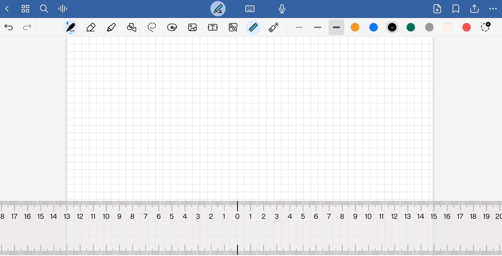
The first step is to open the software and create a new document. To help me create straight strokes, I decided to use a grid and a ruler. (Fig. 1).

Fig. 1. Drawing ruler

Step 2: Shape Tool

Once you have the grid and the ruler selected, you choose the shapes tool and trace your initial figure, in my case, a rectangle. (Fig. 2).

Fig. 2. Shape tool
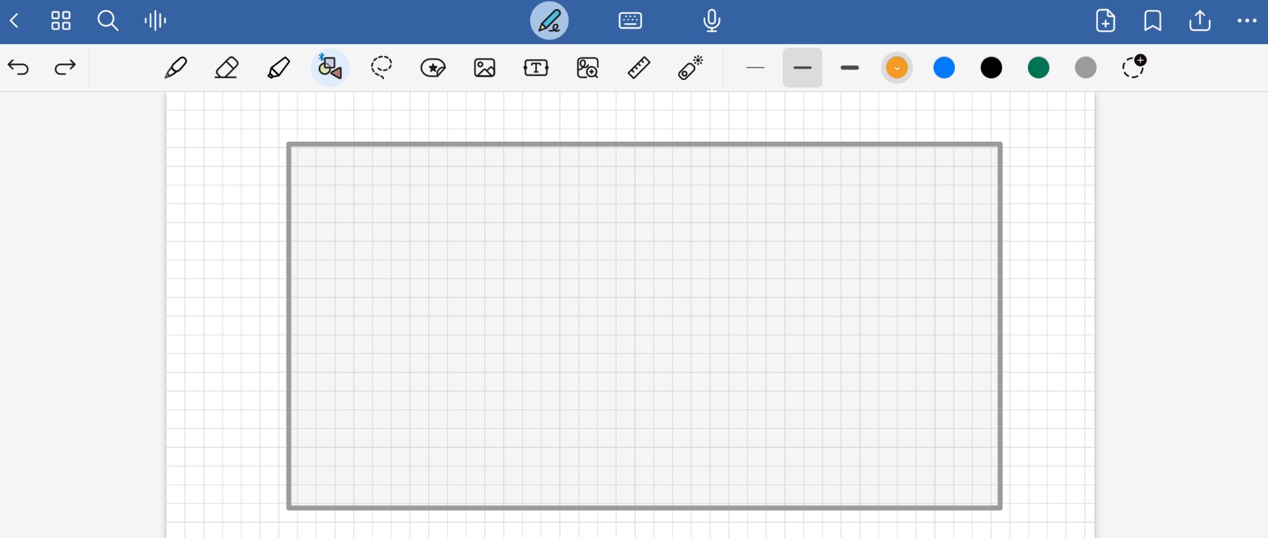
Fig. 2. Shape tool

Step 3: Add a smaller rectangle in length

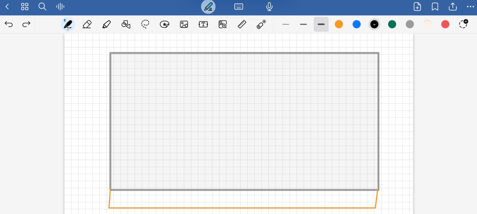
Adjacent to the large gray rectangle, create a smaller rectangle in length but with the same width. Add some angled lines, as the idea is for this to be a small ramp. This is the front of your sketch. (Fig. 3).

Fig. 3. smaller rectangle in length.

Step 4: Left side

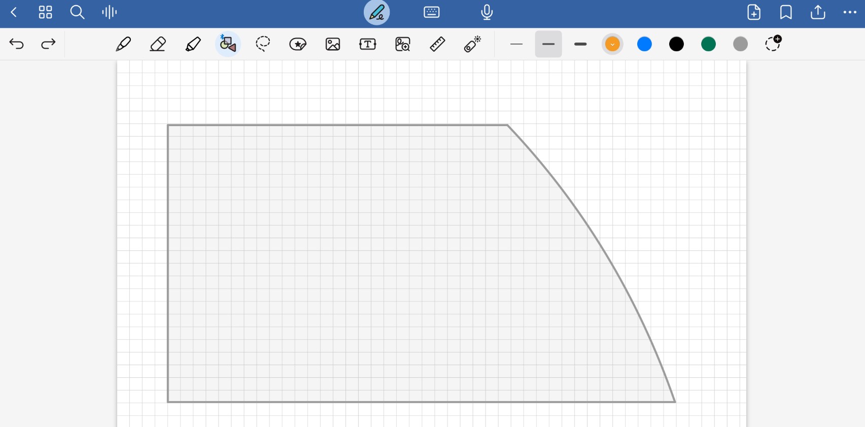
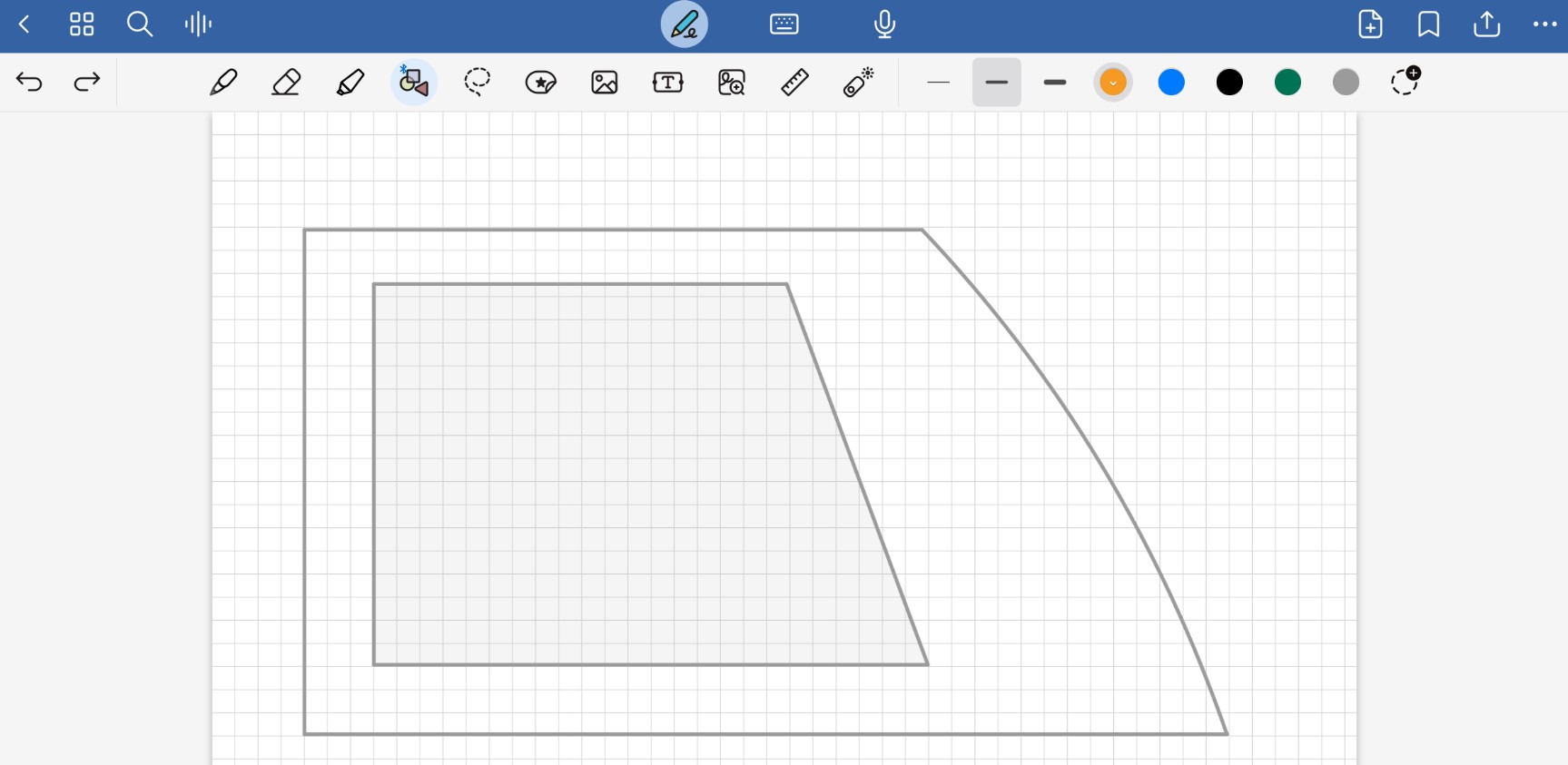
On a new sheet, add a new shape; this time, it should be a rectangle, but on the right side, leave an arc, as this is where it will be assembled to the other figure. (Fig. 4).

Fig. 4. Rectangle with an arc.

Step 5: Smaller scale

Add the same shape, but in a smaller scale, in the center of the previous one; later, this will serve as a cutout to reduce the weight of the robot. (Fig. 5).

Fig. 5. Cutout to reduce the weight of the robot.

Step 6: Wheels

In the design, add a orange circle at the bottom, which will serve as one of our wheels. Duplicate this design in mirror to have both sides of the robot. (Fig. 6).

Fig. 6. Left side of the robot.
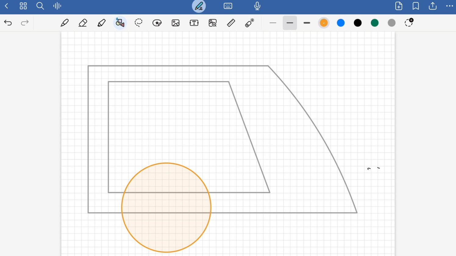
Fig. 6.  Left side of the robot.

Software 2: Illustrator

The next application used for 2D modeling is from the Adobe suite and is called Illustrator. This application allows for the creation of vector drawings, which enables precise visualization of the strokes and the ability to scale them as needed. It is one of my favorite programs due to my greater experience with it and the variety of tools it provides.

Step 1: Open new document

Open Illustrator and select New File. Choose the canvas size you want to work with; in this case, I selected an A4 size, which I can redesign and adjust to a size that suits my needs once I finish.(Fig. 7).

Fig. 7. New file
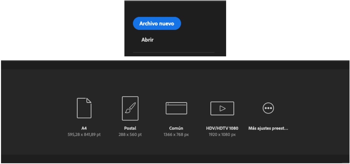
Fig. 7. New file

Step 2: Drawing your sketch

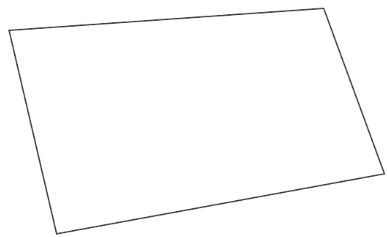
Select the tool that suits you best; in this case, I chose the Pen tool (P) as it provides more precision in my strokes. The sketch I am creating is the isometric viewisometric view of my robot, so my first shape will be a parallelogram or inclined rectangle. (Fig. 8).

Fig. 8. New shape inclined rectangle

Step 3: Add the ramp

Add a rectangle with the same width but shorter in length, and slightly more inclined to simulate that it is a ramp. This is the front of your robot. (Fig. 9).

Fig. 9. Front of you robot.
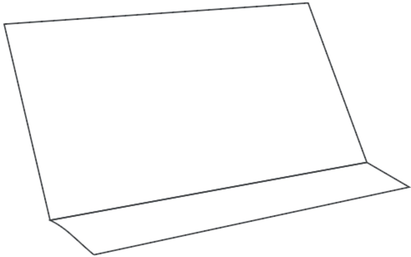
Fig. 9. Front of you robot

Step 4: Complete the ramp

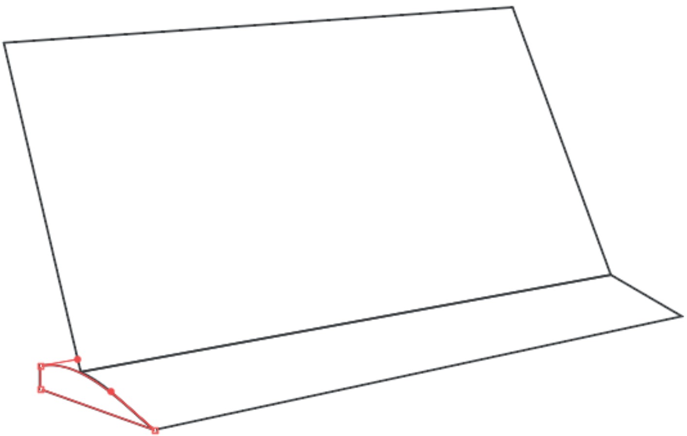
Draw a small arc on the bottom left side to complete the ramp.(Fig. 10).

Fig. 10. Complete de ramp - isometric view

Step 5: Cutout of the left side

To create one of the side walls of the robot, draw a rectangle that respects the frontal shape of it. Inside this rectangle, draw a smaller rectangle that will later function as a cutout to prevent the robot from weighing too much.(Fig. 11).

Fig. 11. Cutout to reduce the weight of the robot.
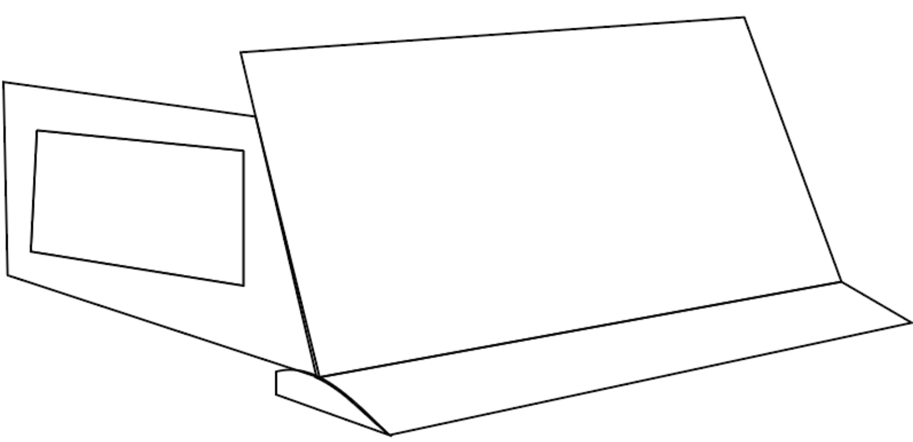
Fig. 5. Cutout to reduce the weight of the robot.

Step 6: Rear side

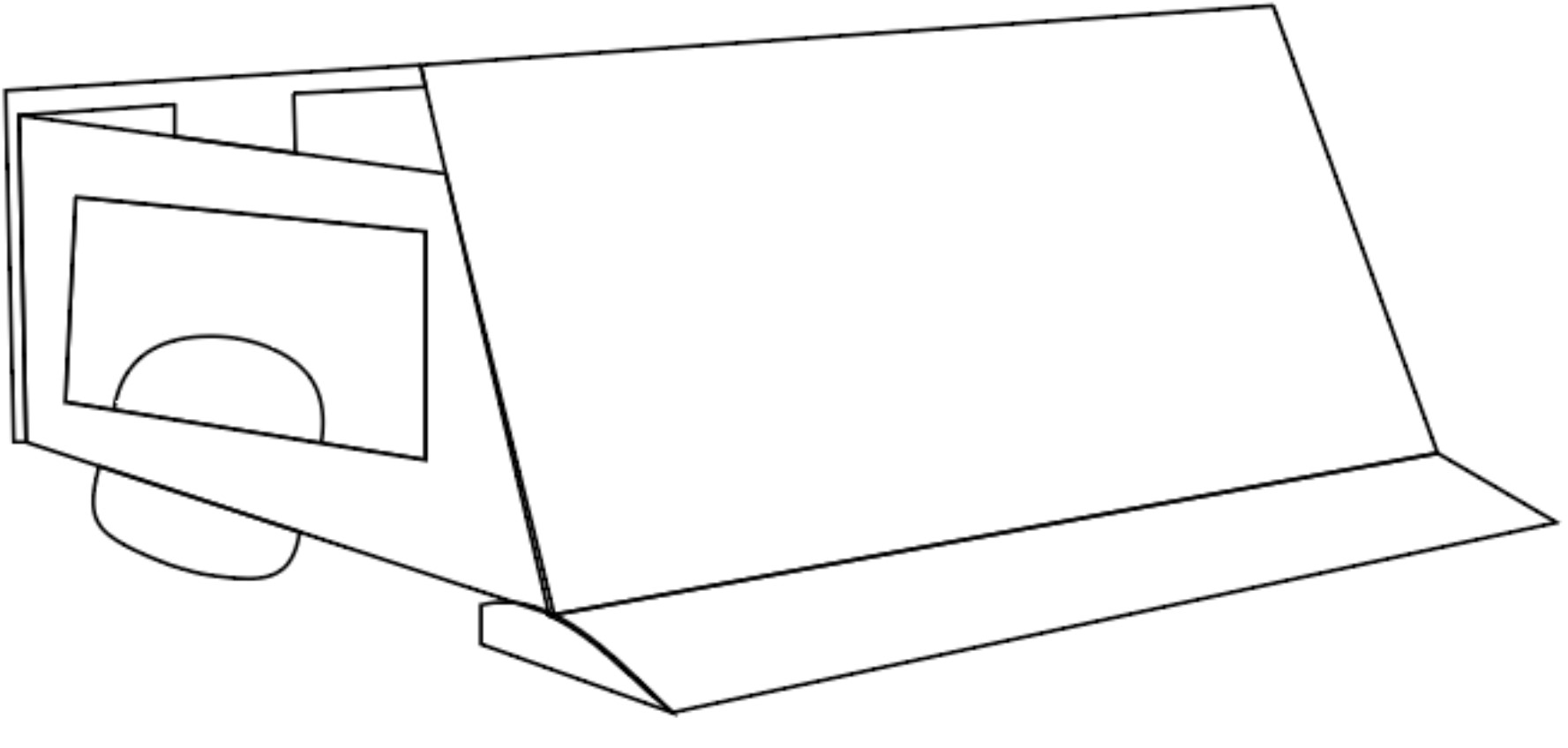
Add the rear side of the robot, leaving some spaces that will serve as cutouts again to prevent the robot from being too heavy and to allow for easier movement.(Fig. 12).

Fig. 12. Left side of the robot.
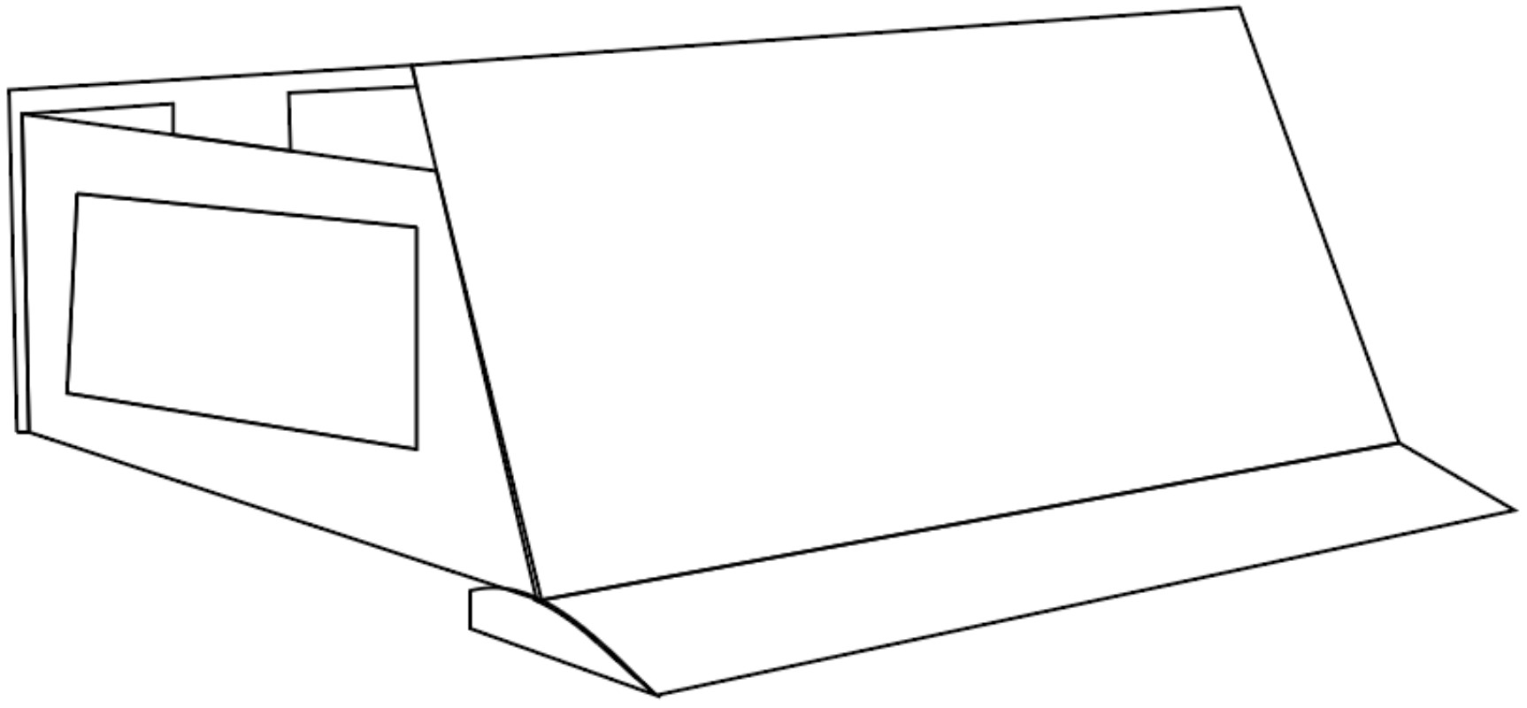
Fig. 6.  Left side of the robot.

Step 7: Wheels

Add a circle that protrudes from the side cutout and also from the bottom left side. This will be one of the wheels of our robot.(Fig. 13).

Fig. 13. Wheels of the robot in isometric view

Step 8: Color

Add color to our sketch; it can be any color. I preferred to use a gray color for the metallic parts and highlight additional elements such as the ramp and wheels in orange to make them stand out.Fig. 14).

Fig. 14. Robot in isometric view.


Step 9: Final sketch

In this image, we can appreciate our 2D design of the robot, with markings indicating the components in an isometric view.(Fig. 15).

Fig. 15. Markings indicating
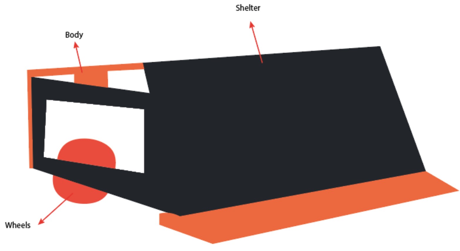
Fig. 15.  Markings indicating

Conclusion

2D design tools are very useful for image editing or prototype design. GoodNotes is a basic tool that allows us to create vectors and drawings in a simple and straightforward way. However, it does not have the wide range of editing tools that Illustrator offers. Therefore, for future 2D designs, I will be using Illustrator.
Documents (.sldprt)

3D Modeling Guide

Getting Started

For 3D modeling, two software programs were used: Thinkercad and SolidWorks.

Software 1: SolidWorks

Step 1: Base Design

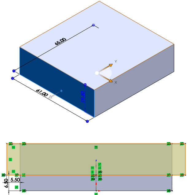
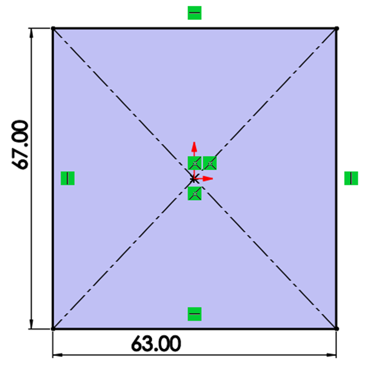
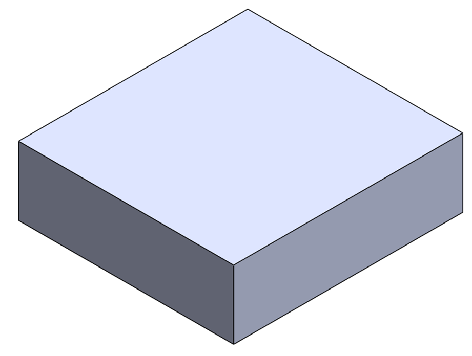
For 3D modeling, it was decided to design the chassis and protective cover of the sumo robot. As a first step, a plan with a top view is opened, and using design tools, a rectangle of 67 mm x 63 mm (Fig. 1) is drawn and extruded to 19.5 mm (Fig. 2).

Fig. 1. Top View
Fig. 1. Top View
Fig. 2. Extrusion of 19.5 mm

Step 2: Shell

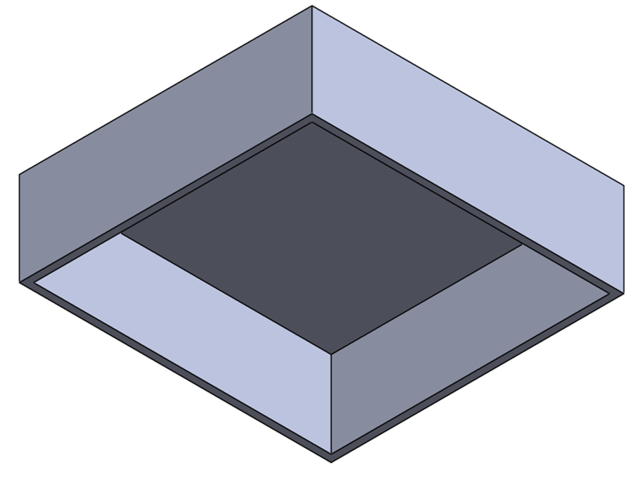
Subsequently, I use the Shell tool to make an internal cut in the material and maintain a wall thickness of 1.5 mm. The robot's batteries will be placed in this space (Fig. 3).

Fig. 3. Shell tool.
Fig. 3. Shell tool

Step 3: Motors’ base design

Next, to design the base where the wheel motors will be installed, the front face of the piece is selected, and a plane is added on it. Then, using the SolidWorks rectangle tool, the geometry shown in the following (Fig. 4).

Fig. 4. Motor Base.
Fig. 4. Motor Base.

Step 4: Extruding the motor base

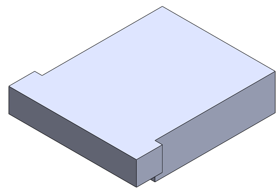
After completing the dimensions of the part, using the SolidWorks extrude tool, 15 mm of material was added to the solid, as shown in Fig. 5.

Fig. 5. Extruding motor Base.

Step 5: Ribs

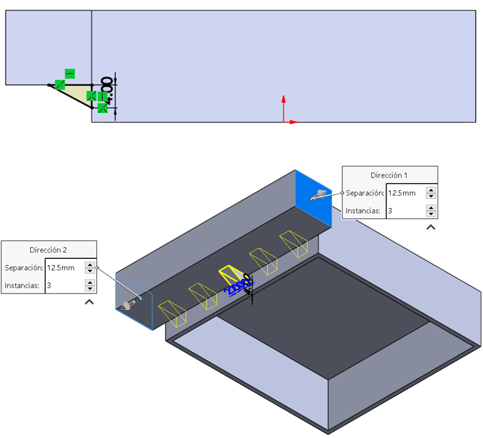
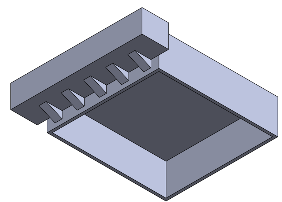
To prevent material deformations due to weight, it was necessary to add 5 ribs, spaced 12.5 mm apart between each of them, between the base and the motor support, as shown in Fig. 6. & Fig. 7.

Fig. 6. Ribs.
Fig. 6. Ribs.
Fig. 7. Ribs extruded.

Step 6: Motor base cut

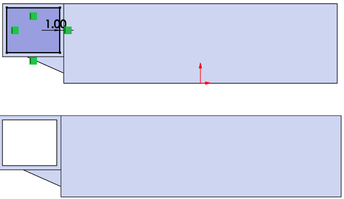
To make the cut where the robot's motors will be mounted, a plane is placed over the side view of the part by selecting the rectangle. Using SolidWorks' 'Equidistance entities' tool, a frame is added with a parameter of 1 mm. This way, SolidWorks will draw a rectangle with a 1 mm gap from the reference frame. Subsequently, a 'Cut-Extrude' is performed 'Through All' to create the internal cavity where the motors will be placed (Fig. 8.)

Fig. 8. Ribs extruded.

Step 7: Protector holder

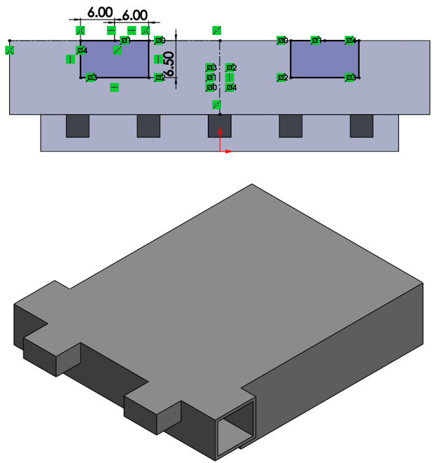
Subsequently, the base is designed to hold the protector that will be used to ram into opponents. A face of the base is selected, and a plane is added. Then, two rectangles of 12x6.5 mm are symmetrically placed, and a 9 mm extrusion is performed (Fig. 9.).

Fig. 9. Protector holder.
Fig. 9. Protector holder

Step 8: Fastening hole

Likewise, holes for fastening are designed. A construction line is placed from vertex to vertex of each rectangle to locate the center of the square, and subsequently, a point is placed at this center. Then, using the SolidWorks Hole Wizard tool, an M4 threaded hole is added with the 'Hole' tool.(Fig. 10.)

Fig. 10. Fastening hole.

Step 9: Cut for wheel support.

Finally, taking the center of the rectangle cut, a construction line of 49 mm in length is drawn. Using the rectangle tool, the circumference of 5 mm in diameter is outlined, and with the SolidWorks cut tool, a through cut is made. (Fig. 11.)

Fig. 11. Cut for wheel support.
Fig. 11. Cut for wheel support

Protector

Steps

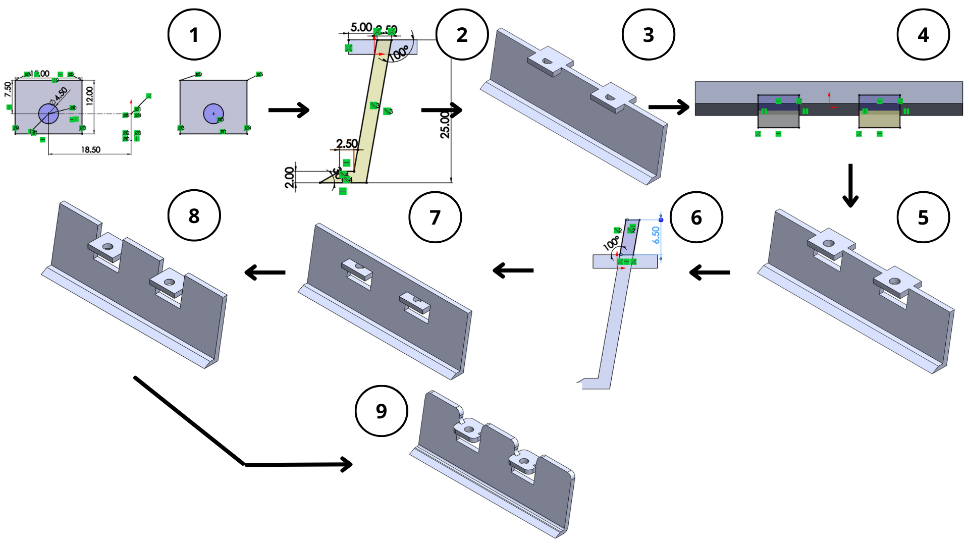
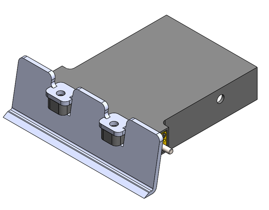
As a first step, a top view plane is selected to design the 12x12 mm rectangles and 4.5 mm holes that will be attached to the main base (see Fig. 12. 1). Subsequently, with a side view of the piece, the protective wall is designed, whose function is to push and lift opponents (Fig. 12. 2). This plane is extruded with material of 49 mm in length, as shown in (Fig. 12. 3) To mount the protector with the main base, it was necessary to draw 2 rectangles (Fig. 12. 4) and make a downward cut of 12 mm (Fig. 12. 5). On the other hand, the protector is extended an additional 6.5 mm to cover the exposed electronics. Finally, cuts are made upwards since the previously extruded material blocks the fastening holes (Fig. 12. 7 - 12.8). To increase the material's resistance, 3 mm fillets were added to the joints and corners using the SolidWorks Fillet tool, as shown in (Fig. 12. 9)

Fig. 12. Steps for the design of the protector.

Final step: Assembly

After completing the parts, a new document is opened, and the assembly option is selected. Subsequently, the created parts are chosen, and the assembly is carried out with their respective 'position relations'. (Fig. 13)

Fig. 13. Assembly.
Fig. 13. Assembly.

Documents (.sldprt)

Software 2: Thinkercad

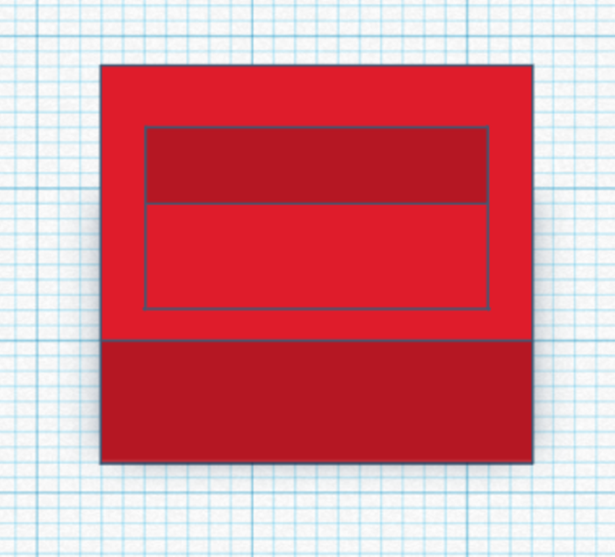
Tinkercad is a free online 3D modeling, electronics, and coding program that runs in a web browser. For this practice, I decided to create a square figure with an internal cut, simulating the base designed in Fig. 3.

Step 1: Box

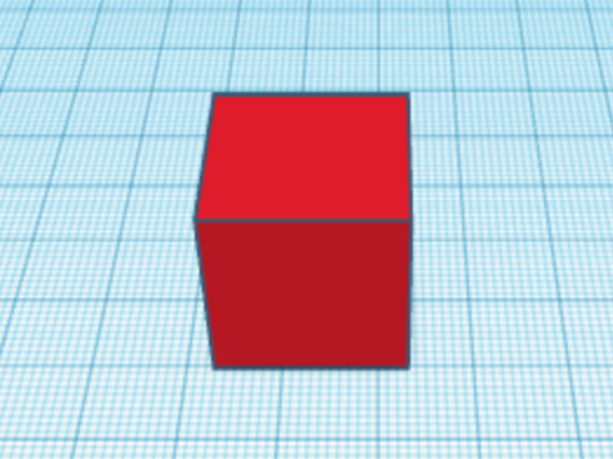
As a first step, in the toolbar, 'Basic shapes' is selected, and the 'Box' tool is chosen to subsequently place it in the top view, as shown in Fig. 14.

Fig. 14. Box.
Fig. 14. Box.

Step 2: Size

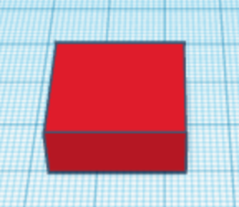
Next, the cube is resized to the desired parameters, as shown below in Fig. 15.

Fig. 15. Size.
Fig. 15. Size.

Step 3: Cut

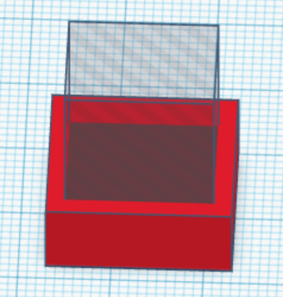
Next, the cube is resized to the desired parameters, as shown below in Fig. 16.

Fig. 16. Step before cutting.

Finally, both pieces are selected, the 'Lock editing' option is selected, and then deselected. Subsequently, it is observed that the 'Group' option is enabled, and then selected, noting that the piece is cuttig (Fig. 17.)

Fig. 17. Cut.
Fig. 17. Cut.

Conclusion

The CAD design software Thinkercad is a very simple tool, but incomplete, unlike SolidWorks. For the design of basic and simple parts, Thinkercad might be an attractive tool, as well as FreeCad. However, based on my experience, SolidWorks has a greater number of tools that allow us to design parts as complex as the user desires, in addition to its widespread use in the industry. Therefore, for 3D part design, I will be using SolidWorks.

Render

The rendering was done using 2 tools: SolidWorks & Vizcom.

Vizcom

Vizcom is an Ai-powered creative tool designed for design and creative professionals. It offers a transformative approach to concept drawing.

Step 1:

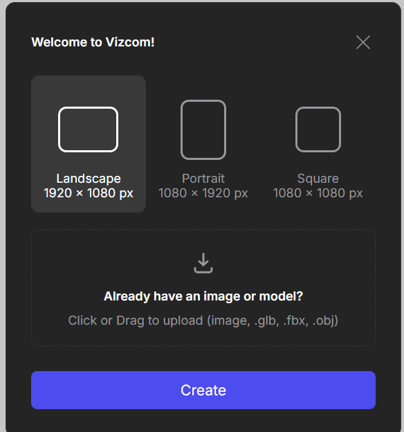
To design the render, I exported Fig. 12 as a .jpg image. (Fig. 18.)

Fig. 18. Upload Image.

Step 2:

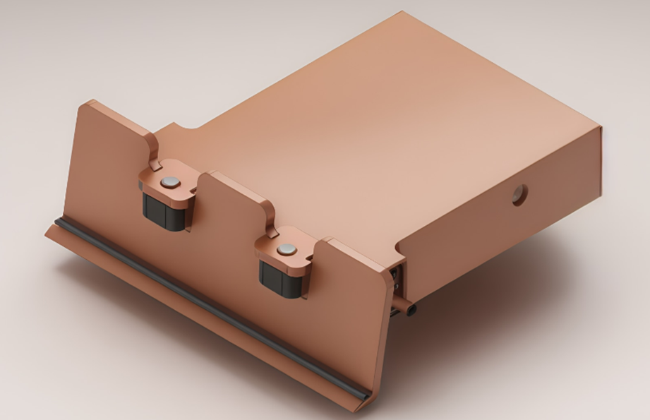
Afterwards, I added the prompts 'sumo robot, 4k, render' corresponding to the sumo robot that was designed. The result is presented in Fig. 19.

Fig. 19. Upload Image.

SolidWorks

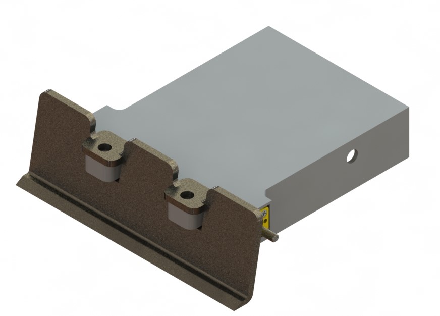
Another software that allows rendering is SolidWorks. Due to my experience with the application, I decided to use it. The process is very simple; you must already have the 3D design of the model to be rendered. Subsequently, in the menu, select SOLIDWORKS Add-Ins/PhotoView 360, which opens the new Render Tools tab/Final Rendering, and wait for the software to render the piece according to the assigned materials. The result can be observed in Fig. 20.

Fig. 20. SolidWorks Render.

Conclusion

Both tools are very good. However, my choice for using these software would depend on the stage of development of my prototype. That is, if I already have a CAD representing my idea, I would do the rendering in SolidWorks. On the other hand, if my idea is still in the sketch stage, I would resort to Vizcom to visualize my idea in a more professional manner.

CAD Animation